Ultrasonic Testing
Introduction
 Ultrasonic testing uses high frequency sound energy to conduct examinations and make measurements.
- Ultrasonic examinations can be conducted on a wide variety of material forms including castings, forgings, welds, and composites.
- A considerable amount of information about the part being examined can be collected, such as the presence of discontinuities, part or coating thickness; and acoustical properties can often be correlated to certain properties of the material.
Outline
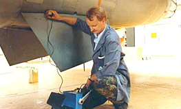
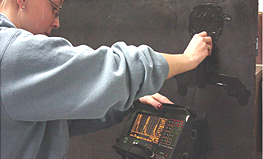
- Applications
- Basic Principles of sound generation
- Pulse echo and through transmission testing
- Inspection applications
- Equipment
- Data presentation
- Transducers
- Instrumentation
- Reference Standards
- Advantages and Limitations
Ultra Sound Generation
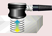 Ultrasound is generated with a transducer.A piezoelectric element in the transducer converts electrical energy into mechanical vibrations (sound), and vice versa.The transducer is capable of both transmitting and receiving sound energy.
Basic Principles of Sound
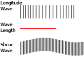 The measurement of sound waves from crest to crest determines its wavelength (λ).
- The time is takes a sound wave to travel a distance of one complete wavelength is the same amount of time it takes the source to execute one complete vibration.
- The sound wavelength is inversely proportional to its frequency. (λ = 1/f)
- Several wave modes of vibration are used in ultrasonic inspection. The most common are longitudinal, shear, and Rayleigh (surface) waves.
- Ultrasonic waves are very similar to light waves in that they can be reflected, refracted, and focused.
- Reflection and refraction occurs when sound waves interact with interfaces of differing acoustic properties.
- In solid materials, the vibrational energy can be split into different wave modes when the wave encounters an interface at an angle other than 90 degrees.
- Ultrasonic reflections from the presence of discontinuities or geometric features enables detection and location.
- The velocity of sound in a given material is constant and can only be altered by a change in the mode of energy.
- Sound is produced by a vibrating body and travels in the form of a wave.
- Sound waves travel through materials by vibrating the particles that make up the material.
- The pitch of the sound is determined by the frequency of the wave (vibrations or cycles completed in a certain period of time).
- Ultrasound is sound with a pitch too high to be detected by the human ear.
Principles of Ultrasonic Inspection
- Ultrasonic waves are introduced into a material where they travel in a straight line and at a constant speed until they encounter a surface.
- At surface interfaces some of the wave energy is reflected and some is transmitted.
- The amount of reflected or transmitted energy can be detected and provides information about the size of the reflector.
- The travel time of the sound can be measured and this provides information on the distance that the sound has traveled.
Test Techniques
 Ultrasonic testing is a very versatile inspection method, and inspections can be accomplished in a number of different ways.
- Ultrasonic inspection techniques are commonly divided into three primary classifications.
- Pulse-echo and Through Transmission (Relates to whether reflected or transmitted energy is used)
- Normal Beam and Angle Beam (Relates to the angle that the sound energy enters the test article)
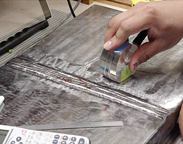
- Contact and Immersion (Relates to the method of coupling the transducer to the test article)
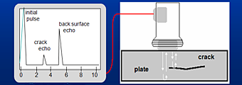
Test Techniques – Pulse-Echo
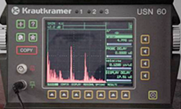
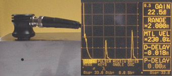 Digital display showing signal generated from sound reflecting off back surface.
- Digital display showing the presence of a reflector midway through material, with lower amplitude back surface reflector.
- The pulse-echo technique allows testing when access to only one side of the material is possible, and it allows the location of reflectors to be precisely determined.
Test Techniques – Through-Transmission
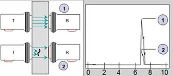 Two transducers located on opposing sides of the test specimen are used. One transducer acts as a transmitter, the other as a receiver.
- Discontinuities in the sound path will result in a partial or total loss of sound being transmitted and be indicated by a decrease in the received signal amplitude.
- Through transmission is useful in detecting discontinuities that are not good reflectors, and when signal strength is weak. It does not provide depth information.